The structural analysis software RFEM 6 is the basis of a modular software system. The main program RFEM 6 is used to define structures, materials, and loads of planar and spatial structural systems consisting of plates, walls, shells, and members. The program also allows you to create combined structures as well as to model solid and contact elements.
RSTAB 9 is a powerful analysis and design software for 3D beam, frame, or truss structure calculations, reflecting the current state of the art and helping structural engineers meet requirements in modern civil engineering.
Do you often spend too long calculating cross-sections? Dlubal Software and the RSECTION stand-alone program facilitate your work by determining section properties of various cross-sections and performing a subsequent stress analysis.
Do you always know where the wind is blowing from? From the direction of innovation, of course! With RWIND 2, you have a program at your side that uses a digital wind tunnel for the numerical simulation of wind flows. The program simulates these flows around any building geometry and determines the wind loads on the surfaces.
Are you looking for an overview of snow load zones, wind zones, and seismic zones? Then you are in the right place. Use the Geo-Zone Tool to determine quickly and efficiently snow loads, wind speeds, and seismic data according to ASCE 7‑16 and other international standards.
Would you like to try out the capabilities of the Dlubal Software programs? You have the opportunity to do so! The free 90-day full version allows you to thoroughly test all our programs.
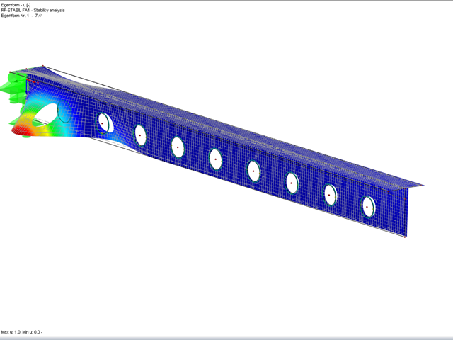
Based only on the surface results or surface stresses, it is not possible to make a statement about the buckling behavior of the box girder. The stability behavior can be analyzed using the RF‑STABILITY add-on module. It determines the buckling shapes and critical load factors that allow a statement about the buckling behavior.
However, the buckling design has not yet been provided. For this purpose, the buckling shape would have to be transferred to the model, so it can be calculated according to the second-order analysis on the imperfect structural system. A stress analysis with the RF‑STEEL add-on module could then be used to carry out a buckling design.
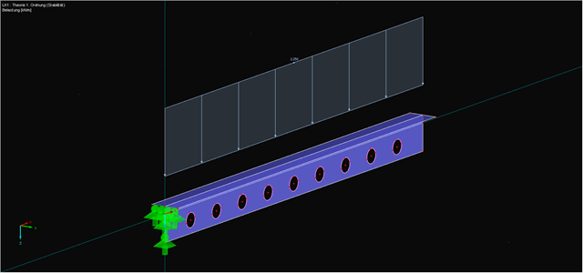
The RF‑IMP add-on module facilitates the transfer of the buckling shape. Using this module, you can generate the equivalent geometry based on the stability mode so that you can perform a buckling design with a second-order stress analysis on the predeformed structure using RF‑STEEL.
The procedure in RFEM could look like this:
As an alternative, you can use the PLATE-BUCKLING module to analyze the buckling behavior.
There are some very interesting technical articles on this topic on our website.
The stability analysis for plate structures can be converted into a pure stress analysis if the calculation is performed according to the second-order analysis and the imperfection required by the standard has been applied to the structure.
Using the RF‑STABILITY and RF‑IMP add-on modules, you can create imperfections (or a predeformed FE mesh). The type of imperfection depends strongly on the structural component and the corresponding standard. For members that have been modeled as a plate structure, you can use the values from DIN EN 1993‑1‑1:2005 5.3. For planar surfaces, it is possible to use the values from DIN EN 1993‑1‑5:2006, Annex C, for example. For shells, the problem is much more complex and there are different approaches. I would advise against the generation of imperfections and perform the plate buckling design using the MNA/LBA concept according to DIN EN 1993‑1‑6, which does not require the application of an imperfection.
For example, if you want to design a surface model of a steel beam, you can proceed as follows:
1. Select a load with relatively high axial forces (compared to other internal forces in the load case), in most cases you can use the self-weight load case or a load combination with the corresponding self-weight. It may be necessary for each load combination to have an individual imperfection.
2. Calculate the load combination according to the linear static analysis and use it as a basis for RF‑STABILITY.
3. Find the first mode shape of a global failure using RF‑STABILITY.
4. Use the calculated mode shape as a basis for an imperfection using RF‑IMP. It is possible to apply 1/300 of the beam length as an amplitude, for example.
5. Create a load case combination that uses the created imperfection as a basis and is calculated according to the second-order analysis.
6. Perform a stress analysis using this load combination, which is also the stability analysis of the structure.